Foreshortened Diameters
If you’ve ever needed to use a foreshortened diameter dimension in your drawings, you’ve likely ran into issues getting them to show up. Maybe it’s just me, but the Help doesn’t give you much to go on…all you get is “When you drag a diameter dimension to another drawing view, and the software detects that the dimension will be too large for the drawing view, the dimension is automatically foreshortened.” That’s all well and good, but that doesn’t tell you everything.
I’ve recently had this issue brought up several times over the past few months, and thought I would document the best way to create them.
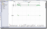
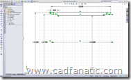
First off, it requires bringing in model dimensions; it doesn’t seem to work with manual dimensions. This means that you need to dimension your model in the same way as you intend to document it on the drawing. You are creating your models this way, aren’t you? Of course you are! It’s all about the design intent!
Actually, I wish this was true… This is the way that you should be modeling in the first place; unfortunately, I have found that this is usually not the case. But I digress…
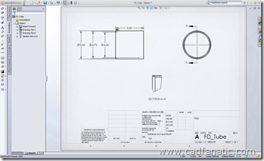
Ok, so you’ve got your model all modeled, and you’re drawing in your drawing. After you get your views laid out, choose Insert Model Items from the Annotations toolbar. The dimensions from the second image above are brought into the drawing:
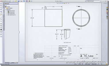
Then, you simply shift-drag the dimensions you wish to use in the cropped section view from the dimensioned view to the desired view:
And there’s your foreshortened diameters!
One thing to note, I’ve noticed that SolidWorks 2008 SP4.0 x64 does some funny stuff when dragging the cropped view around; one or both of the foreshortened diameter dimensions lose their foreshortening when moved certain distances from the other views. However, it seems to work fine in both 32-bit 2008 SP4.0 and 2009PR1.
Do you use foreshortened diameters? If so, how easy was it for you to figure out?


Pingback: Foreshortened Diameters | CADFanatic()