Home » Tips & Tricks, Troubleshooting

New SolidWorks Help Site – SolidJott!

3 December 2008 23 Comments

SolidJott Our friend Ben Eadie of SolidMentor fame has started a new SolidWorks site called SolidJott.  The format is a microblog that anyone can post to (requires a free account) and other users can reply in the comments.  You can add tags to your posts/questions so that you can more easily find them later.  Anyone using Twitter should feel right at home.

There is an RSS feed so that you can get all the posts pushed to you, and Ben is also working on a SolidWorks add-in so that you can post and answer to SolidJott from right within the SolidWorks Task Pane!  Be sure to check the SolidJott site for more information, as this add-in will be going into Beta before long.
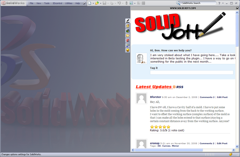
SolidJott Integration With SolidWorks

Post to Twitter Post to Facebook Post to LinkedIn Post to Delicious Post to Ping.fm Post to Digg Post to StumbleUpon Post to Technorati Post to Reddit Post to Slashdot


  • All hail Ben Eadie, master of helping all SW users everywhere. I like the site so far. I think with more SW users getting on Twitter and popping links into their tweets to posts on sites like SolidJott and others will result in quicker answers and problems resolutrions.

  • Dan

    Problem with hole series.

    After updating the locations of holes used to create a hole series in an assembly, I have both the old holes and the new holes in the affected part — looks like I took a counterdrill and and moved it sideways. Update doesn't fix it, and I can no longer delete that feature from the part. Familiar to anyone?

  • Hi Dan,

    I do not use the Hole Series function, so I am at a loss here… Might could be a graphics issue?

    You might try posting the question at the SolidJott site at http://solidjott.com/.

  • Hi Dan,

    I do not use the Hole Series function, so I am at a loss here… Might could be a graphics issue?

    You might try posting the question at the SolidJott site at http://solidjott.com/.

  • MARTINJERRY

    I HAVE A NEED TO PLOT FULL SCALE (1:1). ARE THERE ANY PLOT DRIVERS AVAILABLE FOR SW. I AM USING A HP DESIGNJET 430.

  • The HP drivers have always worked fine for me plotting to large format from SolidWorks. You can set 1:1 scale in the printer driver settings.

  • MARTINJERRY

    APPARENTLY MY DRIVER/PLOTTER IS OLD. I DO NOT HAVE THE SCALE 1:1 OPTION. MY ONLY CHOICE IS 100% BUT THIS SCALES TO FIT A FORMAT SIZE?

  • Are you trying to print from the model or a drawing?

    Yes, I did misspeak on the 1:1 setting; it is 100%

    There is not a way to ensure a print of 1:1 from the modeling environment ARAIK, but if you are printing from a drawing, the 100% setting should print your drawing 1:1 scale for the selected paper size (i.e., D-size drawing to D-size sheet).

    If you are wanting a 1:1 print of the model, you can put a full size view of it (1:1 scale) in a drawing and change the drawing sheet size to encompass it and then print at 100% with the custom sheet size specified in the printer settings.

  • MARTINJERRY

    Brian
    Thankyou
    Worked perfect. Good tip
    Thanks again

    Jerry

  • rmansfield

    Hi – I am needing to create in SW09 a 1″ dia. OD pipe, 30″ long with both ends having the effect as if they were crushed in a vice about 1″ back from each end. Any ideas ?

  • Rodney,

    Since this involves material deformation, I don't think that SolidWorks has a easy way to show this. So the end CAD result that you want will determine what you need to do.

    If you are after a truly accurate model, I think you would have to actually for th epart in the shop and then use some measuring and surfacing to rengineer the ends in SolidWorks.

    The way I would approach modeling this is just to have a simple model with smaller ends like so:

    <img src=”https://www.cadfanatic.com/wp-content/uploads/2009/07/PipeVise-300×194.png” alt=”Pipe From Vise”>

    (Download file here>.)

    It doesn't look as realistic, but I think suffices for a CAD model/drawing.

    You could post this question on the site mentioned in the article above, http://solidjott.com/, and you might get some more tips…

  • rmansfield

    Hi Brian,

    Thanks for your help. I kind of knew in the back of my mind that I would have to do that, but I was hoping I was wrong. Once again, I appreciate your timely response.

    Rodney

  • renevb

    I have created a part where I wanted a weldment. I have completed all of the design on this unit and I can not create a cut list. Is there anyway to delete parent/child relationships?

  • You can change a part into a weldment with a few steps…

    So, I take it that you didn't create it using weldment tools? I'm also assuming you mean the relationships between the features…

    If you have the part created as one body, you can break the bodies out manually by editing the respective feature definitions and uncheck the “Merge result” box. This will create the multiple bodies. I think to get the Cut List, you will have to add a Weldment feature at the beginning of the Feature Manager…

  • You can change a part into a weldment with a few steps…

    So, I take it that you didn't create it using weldment tools? I'm also assuming you mean the relationships between the features…

    If you have the part created as one body, you can break the bodies out manually by editing the respective feature definitions and uncheck the “Merge result” box. This will create the multiple bodies.

    To get the Cut List, you will have to add a Weldment feature at the beginning of the Feature Manager.

  • lisamarie47

    I am pulling up a huge assy on my laptop and trying to make some views for dimensions that I need to get sent off tonight. My drawing views keep disappearing when I zoom in and out. I think it is because I don't have enough memory. Is there anyway to do this differently so that not as much memory is used?
    Despartely Wanting to finish!

  • Lisa,

    Sorry I haven't responded sooner. I have been out of pocket lately, and am now trying to get caught up on emails.

    I know it's probably too late, but I would try to create simplified configurations of all the subassemblies and parts. For example, if you have a subassembly that has a lot of components that are not shown at the top level, create a new configuration and suppress those hidden components. If you have a complicated part, suppress some of the features that do not show up at or really affect the top-level, such as fillets, internal ribs, etc.

    Brian

  • susiladewi

    Hi Brian
    Good tip. Worked perfect.
    Thanks

  • Hi Brian
    Good tip. Worked perfect.
    Thanks

  • Rodney Mansfield

    Hi all – I recently updated to SW 2012 SP0.0. The software worked very well for a few weeks then all of a sudden it is taking (literally – I timed it) 5+ minutes to initially launch the software. After it is open – the system is so slow, it takes forever to do anything productive. I’m using a quad core (Q6600) intel processor with 8G RAM along with an NVIDIA QuadroFX 4500 dual GPU with 1GB DDR3 RAM video card. Windows Ultimate 64 Bit is the OS. Strangely enough my SW 2011 & SW2010 are also operating very slow. Any Ideas would be greatly appreciated. I’ve reinstalled the software several times – it boots & works great ….. only the first time it’s launched.

  • Free_iran

    hi friend,
    I have a simple problem with the part section of solidworks, I have drawn two shapes in the part section and need to minuse one of them from the other, as a result the volume of the second shape would be cut away from the first shape and its empty volum would remain on shape 1 like a curved cut
    but I can’t find an order for it, please guide me

  • Kadrozd

    Just installed the 2012 SW. I have a 90 degree angle on a part.  I have the corner filleted which needs to remain that way.  Then when I go to chamfer the edges that lead to the fillet the program chamfers everything. I cannot just select an edge and chamfer, it continues around the 90. Point is no chamfer on top of the fillet. Any ideas?

  •  Hi Kadrozd,

    I think I am picturing what you are describing…if I am correct, I have ran into this before.

    One thing you could do is put the chamfer feature before the fillet.  If this doesn’t give you what you want, I think you will have to create the chamfer manually with a Cut-Extrude or another feature.