CADFanatic’s Tips & Tricks Tuesday – Derived Sketches
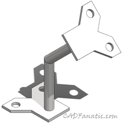 How do you recreate an identical sketch on another face/plane? Convert edges is fine if you want to project a sketch to a parallel face or plane, but what if the face in question is not parallel? You could copy a sketch and then mess around with linking all the dimensions, but what if you want the sketch in a different orientation? Enter the Derived Sketch command.
The Derived Sketch is a cool tool; it creates a copy of a sketch that is tied back to the original. After deriving a sketch, it’s only a matter of orienting and positioning it in its new location.
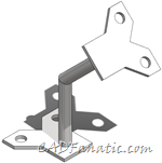
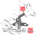
Take the leg brace weldment shown above for example. A Derived Sketch will allow you to keep your design intent by ensuring that the two end flange plates are always the same shape and size. Let’s look at how it works.
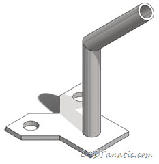
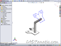
First, you create one of the plates as you normally would:
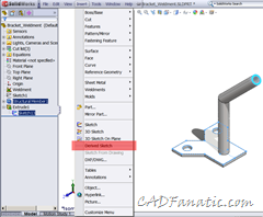
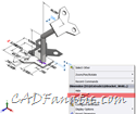
Then, you select the original sketch and the face or plane you wish to position the new sketch on and choose Insert|Derived Sketch:
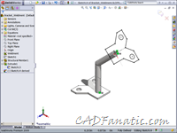
Now it’s just a matter of orienting and positioning the new sketch. Any changes to the original sketch will be reflected in this sketch as well.
To finish things off and make sure that the full design intent is there, you can link the thicknesses of each plate:
So there you have it! A couple of things to note is that you cannot add any additional geometry to the Derived Sketch, and in this 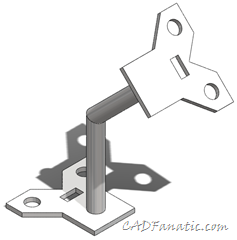 example I had trouble getting some of the constraints to work out like I wanted. Also, any new geometry added to the original sketch will be propagated to the Derived Sketch.
In the image to the left, a square cutout was added to the lower base bracket, and you can see that it was propagated to the upper bracket.
Do you have any special tips or tricks you use to make working with SolidWorks faster or easier? Email them to us at [email protected] and it may be featured on a future CADFanatic’s Tips & Tricks Tuesday!



Pingback: CADFanatic’s Tips & Tricks Tuesday - Derived Sketches, by Brian McElyea()