Home » Design Resources, Tips & Tricks

3 Ways To Model The Same Thing

18 August 2009 17 Comments

If you haven’t noticed, people are different.  They have different tastes in clothing, food, and music.  You say tomato, I say ‘mater.

So it follows that designers will have different modeling methodologies.  Sometimes, even circumstances or desired design intent dictate how you model something.

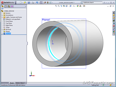
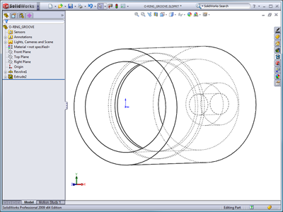
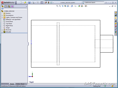
Take for instance this simple part with an o-ring groove in it:

O-ring Groove

I had a new SolidWorks user approach me a while back with the question, “How do I create something like this?”

I responded by showing them several different methods to achieve the same result.

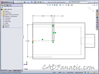
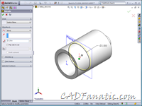
One approach would be to do a Cut Revolve:

O-RING_04 O-RING_05

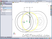
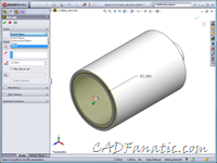
Another method (and what I believe a lot of folks would do) would be to offset a plane from the end and sketch the profile to cut:

Select face to offset plane from Sketch on offset plane

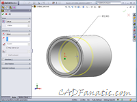
Then, simply do a Cut Extrusion:

Cut Extrude from offset plane 
I’m not really a fan of this method, unless your design intent requires the plane for something else (i.e., aligning the o-ring), as I try to have as clean a Feature Manager as possible.  Sometimes, work geometry can clutter up things…

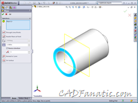
Another option, which is similar to the last yet may be unfamiliar to you, eliminates the creation of an offset work plane.  You simply create the sketch on the existing end face and then do a Cut Extrude, offsetting the start of the cut.

O-RING_06 O-RING_07

All of the above methods yield the same result, albeit with varying features and number of features:

O-RING_08

Of course, there are multiple other ways that this could be accomplished, perhaps some better than these.  The o-ring groove could even have simply been modeled in the original sketch, although that may not be considered a “best practice” by some…

All of this is to say that there isn’t really a right and wrong way to model.  But sometimes one method is better than the other – and that is your call to make.

(Download SolidWorks 2009 file here.)
Post to Twitter Post to Facebook Post to LinkedIn Post to Delicious Post to Ping.fm Post to Digg Post to StumbleUpon Post to Technorati Post to Reddit Post to Slashdot


  • I am becoming more of a fan of the offset extrusion/cut.

  • Me too! I am using it more and more…it really cuts down on work features.

  • Chris Serran

    Same here, but I really wish there was a way to edit the offset without going into the feature.

  • Agreed…it would be nice if you could access the offset from a double-click. Enhancement request?

  • Pingback: 3 Ways To Model The Same Thing, by Brian McElyea()

  • Steve_Calvert

    I sometimes add the o-ring groove into my original revolve for the part itself.

  • Great idea comparing methods, though an o-ring groove is usually created as a “revolved” feature in the real world (turned), so shouldn't the CAD model follow this?
    Ed

  • As far as modeling reflecting real world procedures; I would not necessarily agree with this. If you modeled everything as it would be actually be made, you would start with a billet and start cutting away – not that there is anything exactly wrong with that, either. I've actually done a few models this way when dealing with structural shapes, and know others that have too.

    I suspect that in this particular case, most folks would just model the groove in with the original revolve…

  • Which option is best if you think you want to modify it later? An o-ring will likely always be circlular but you may want to move it higher or lower in the cylinder.

  • All of the methods but one shown in my post above and including the groove in the main revolve are equally easy to modify with a double click on the sketch or feature or a click and drag with Instant 3D on. The only exception is for the offset cut; AFAIK, that one would require going into the feature definition to change the location.

  • jaiswal utsav

    hi there
    my name is jaiswal utsav.i anm a nechanical engineer

    instead of using cut,it would be better to make the sketch 1st sketch in such a manner so that when u create a rvolve
    it would result in the desired feature ,at once

  • itjobs1

    Great idea
    thank you
    http://www.staffingpower.com

  • itjobs1

    Great idea
    thank you
    http://www.staffingpower.com

  • very useful tips. Thank you.